(Custom PCBs are tailored products; the images and specifications provided are for reference only.)
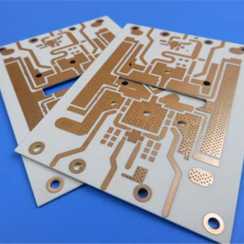
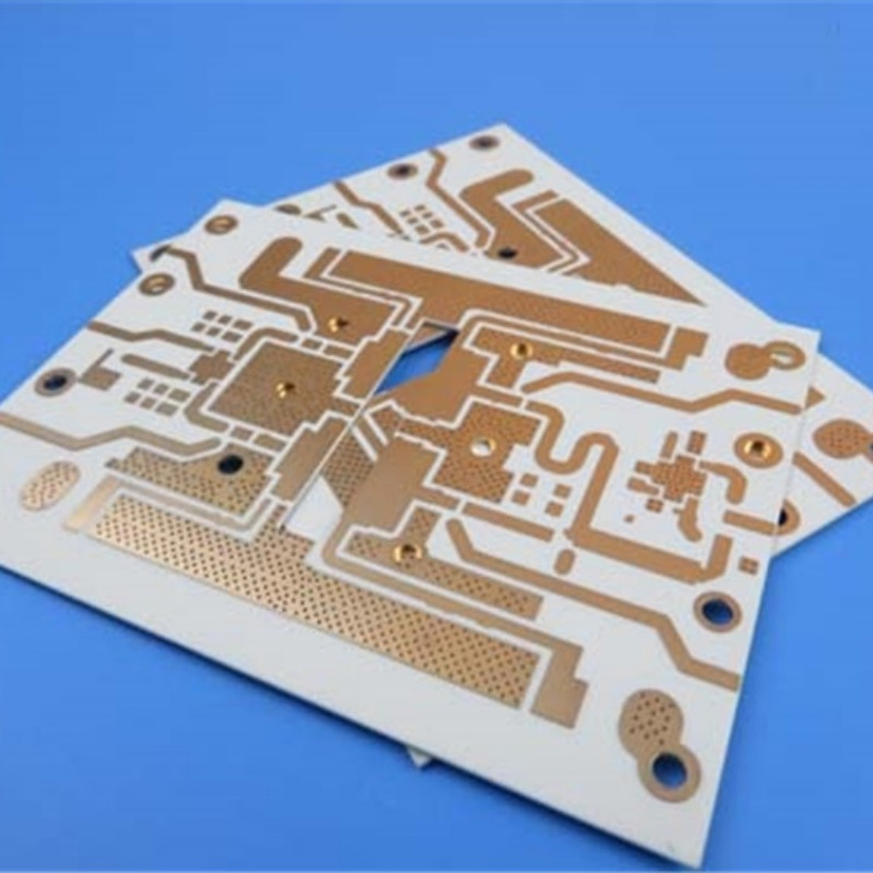
The RO4003C 0.5mm 2-layer PCB is a high-performance, ultra-thin circuit board designed for RF applications requiring both excellent electrical performance and compact form factors. Utilizing Rogers' innovative woven glass reinforced hydrocarbon/ceramic composite, this 0.5mm thick PCB delivers exceptional signal integrity (Dk 3.38±0.05) while maintaining FR-4-like manufacturability. The slim 0.5mm profile combined with its unique material composition bridges the gap between standard FR-4 and premium RF materials, offering the low-loss characteristics of PTFE with the cost-effectiveness of epoxy/glass processing.
Q1: What are the main benefits of using RO4003C over standard FR-4?
RO4003C offers significantly lower dielectric loss and much tighter control over the Dielectric Constant (Dk), making it superior for high-frequency RF applications where signal integrity is paramount.
Q2: Why is the 0.5mm thickness beneficial for modern electronics?
The 0.5mm ultra-thin profile allows engineers to design more compact and lightweight modules, which is essential for 5G mobile hardware, slim automotive sensors, and portable satellite equipment.
Q3: What is the advantage of the Immersion Silver surface finish?
Immersion Silver provides a flat surface for SMT components, offers excellent conductivity for high-speed signals, and is more cost-effective than ENIG while maintaining high reliability.
Q4: Can this PCB handle high-power RF conditions?
Yes, Rogers RO4003C is specifically engineered to withstand high-power RF conditions due to its high thermal conductivity (0.71 W/m/°K) and high glass transition temperature (Tg >280°C).
Q5: What file format is required for production?
Standard production requires Gerber RS-274-X files, though PCB.Doc and other common CAD exports are often supported for custom RF designs.
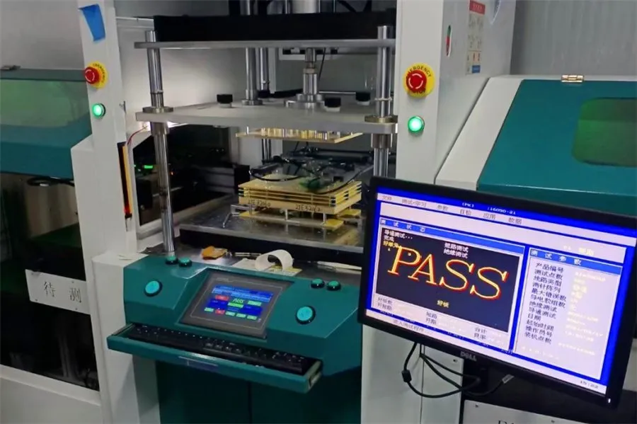
Q6: Is 100% electrical testing standard for these boards?
Yes, all high-frequency PCBs undergo 100% electrical testing prior to shipment to ensure zero-defect performance in critical RF environments.